| Battery Rack | ||
| HOME |

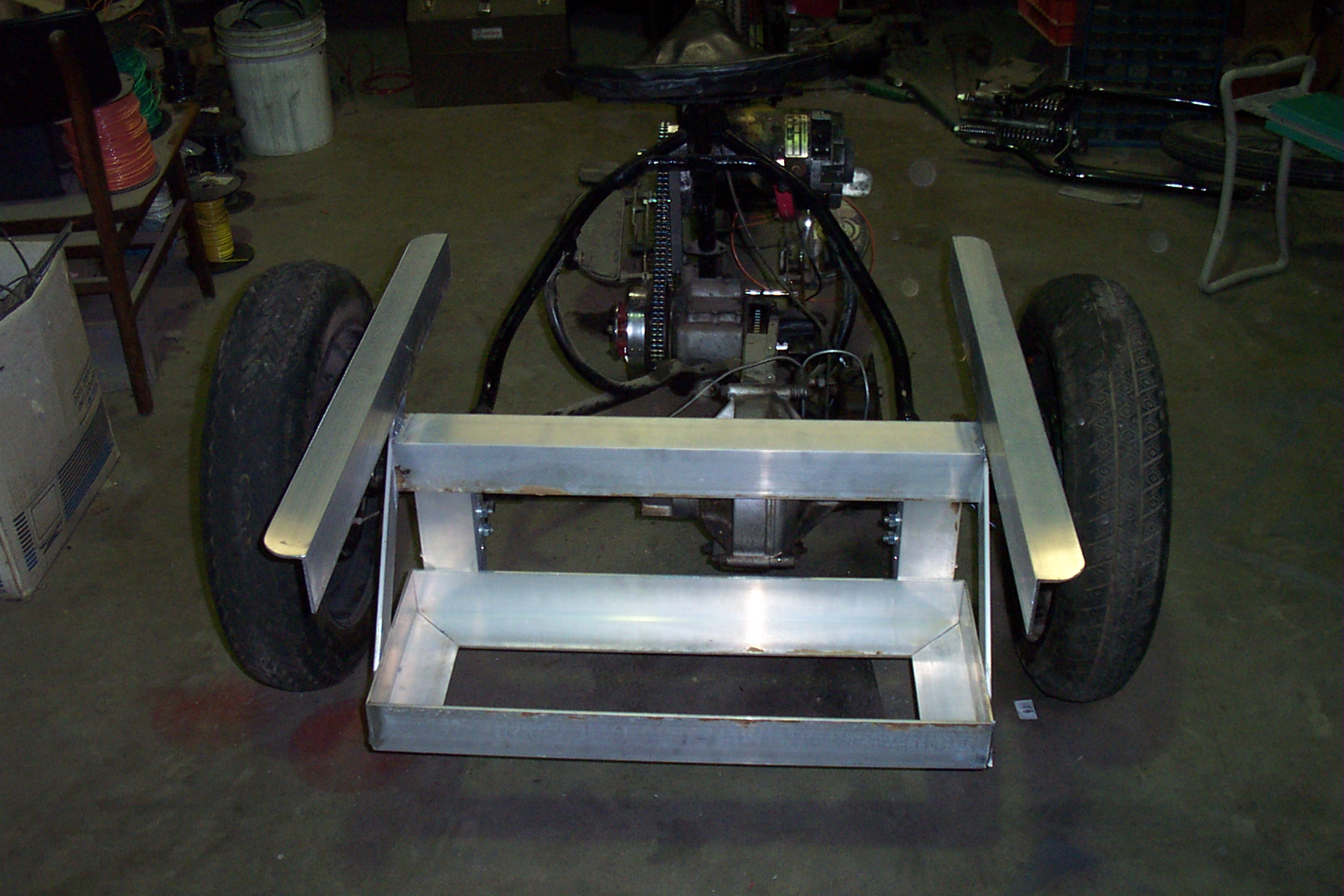
Next I moved on to the battery rack. I am still unsure of how many batteries I will end up with. The first few will go in a rack behind the axel. This will leave room for more possible in the box over the axel as well as one or two up front where the fuel tanks would normally be. Above is the basic framework sized such that I can put 4 batteries side by side. I sized the frame for Trojan T125 6 volt batteries and mounted it low enough that the batteries will be below the floor of the back box. I needed to create some way to support the back box over the batteries and added the framework shown below. The flat bars at an angle are to hold up the back side of the batteries.
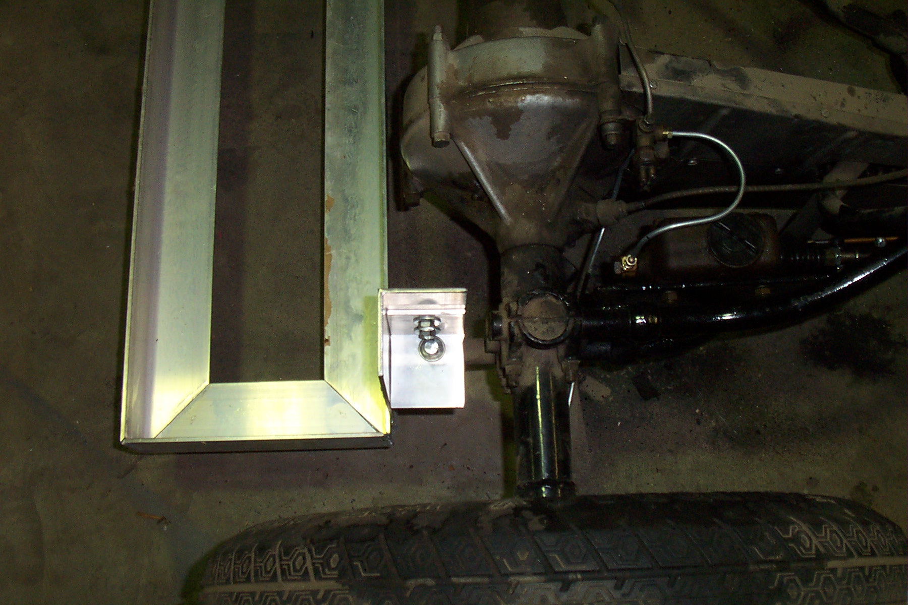
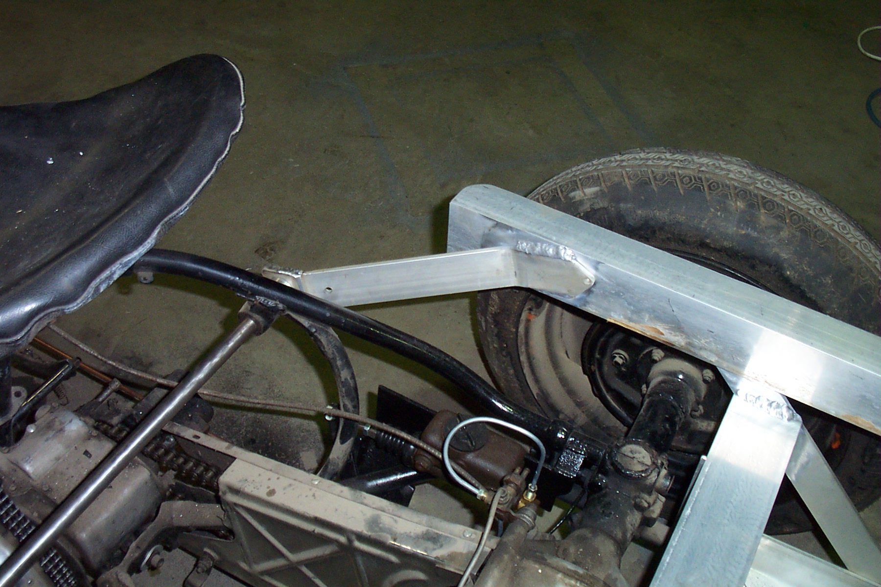
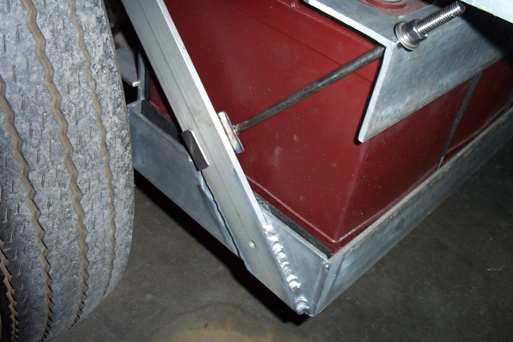
This entire structure is attached directly to the frame at two points and would not be able to support the battery weight or even the box weight during movement. The original mounting for the box was to a cross shaft up front with springs and shocks under it. I re-created the front mount for the aluminum frame to give it the required strength. Here is the rear and front mounting for the framework.
There is still some concern that I may be making a "wheelie" machine, however I think with my weight and any additional batteries mounting forward of the axel, I will be OK. Worst case I'll add wheelie bars at the back. The structure is fabricated out of 3"x3"x1/4" aluminum angle with the braces fabricated out of 1/"x2" aluminum flat bar. The front mounts are doubled up to be 1/2" thick where they are mounted on the 3/4" front mount shaft which is a piece of stainless steel that I had on hand.
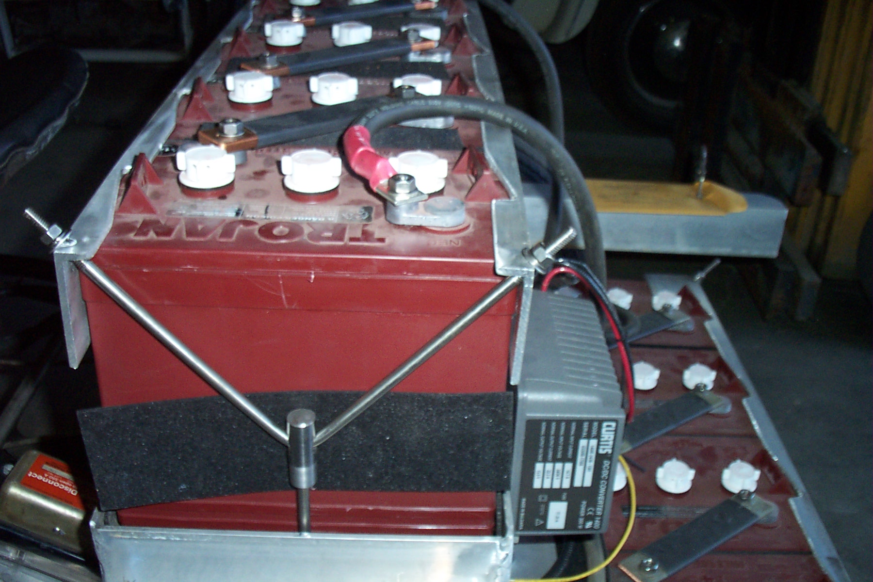
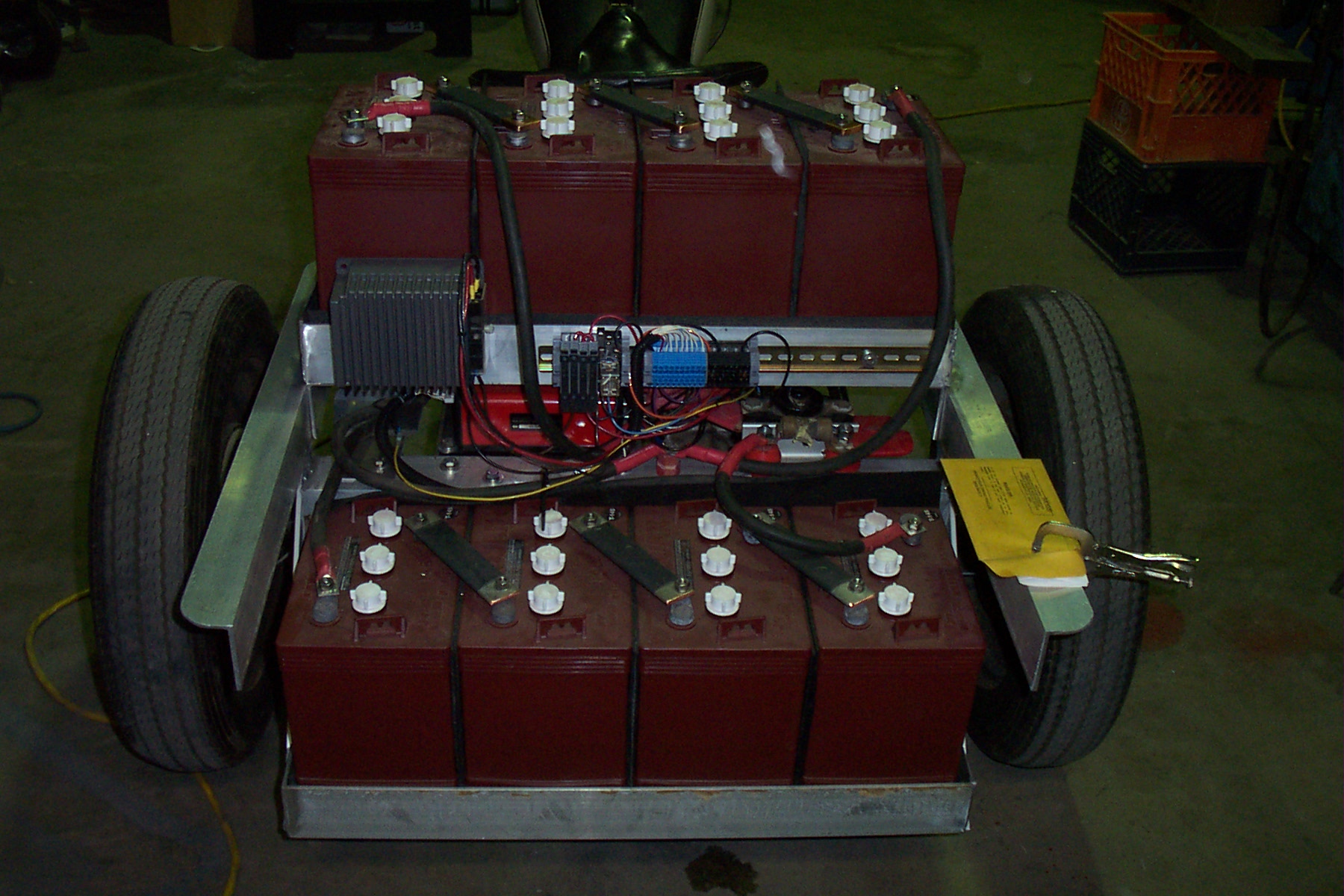
The batteries have now been mounted and tie downs are in place (May 06) Upper rack on the left and lower rack on the right.
A rear view of the batteries in the racks, 24 volts in each rack. The lower rack has the additional load of the DC-DC converter as well as the 24 volt coil of the main power contactor. I have set up the system to be charged as 2 separate strings of 24 volts so the lower string can be kept up with the upper string. I am planning on using a Curtis Battery Fuel Gauge on the lower string as it will be drawn down faster and I will need to tailor my driving to it's capacity. The motor will be run on 48 volts.
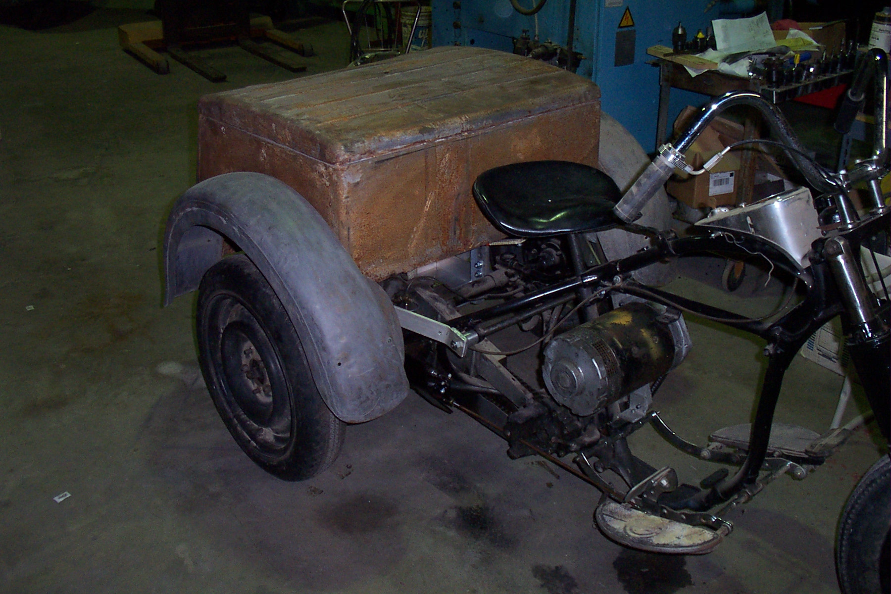
This picture shows the box set on the framework as it is expected to end up. I don't have any skills in bodywork so will have to try to find a body shop to assist in repairing the box next. In the mean time I can begin the planning on the wiring.
|