| Drive System | ||
|
|
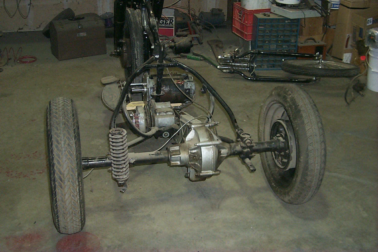
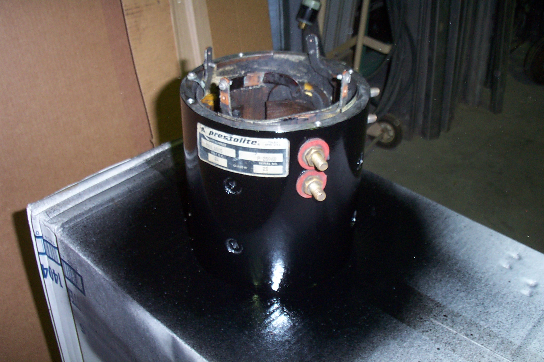
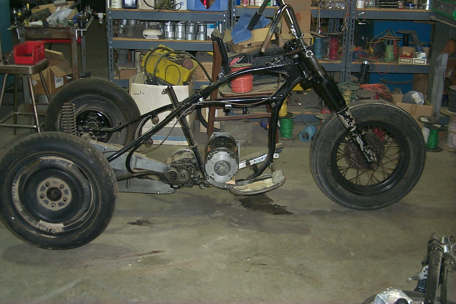 Now on to figuring out the drive arrangement. Above is the glider pretty well stripped down and the electric motor set in to see where it might fit. I had hoped to put the motor behind the seat post, but it just wouldn't fit so it will have to go in the "normal" engine cavity. The problem is that the motor needs to stick out quite a ways on the right side to get the sprockets for the primary drive aligned.
For now I am planning to put the motor in front of the seat post, but up high where it will be under my leg in a riding position and also will leave the foot board clear. There will probably be a little interference with the transmission shifter and I will have to deal with that after the motor is installed.
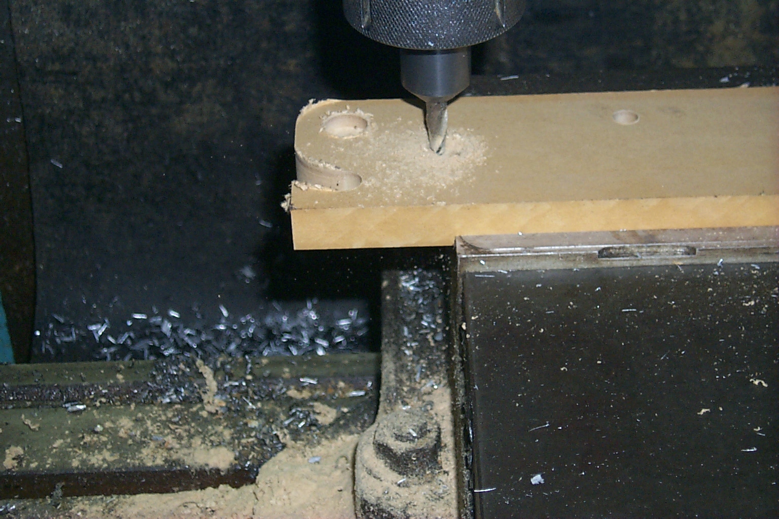
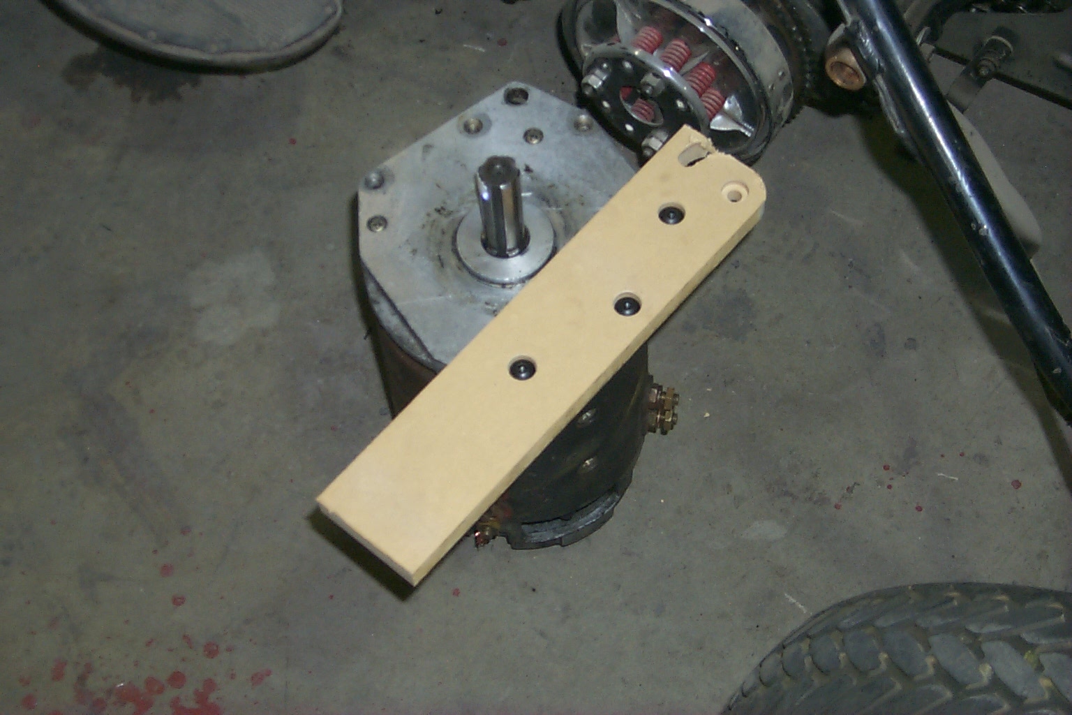
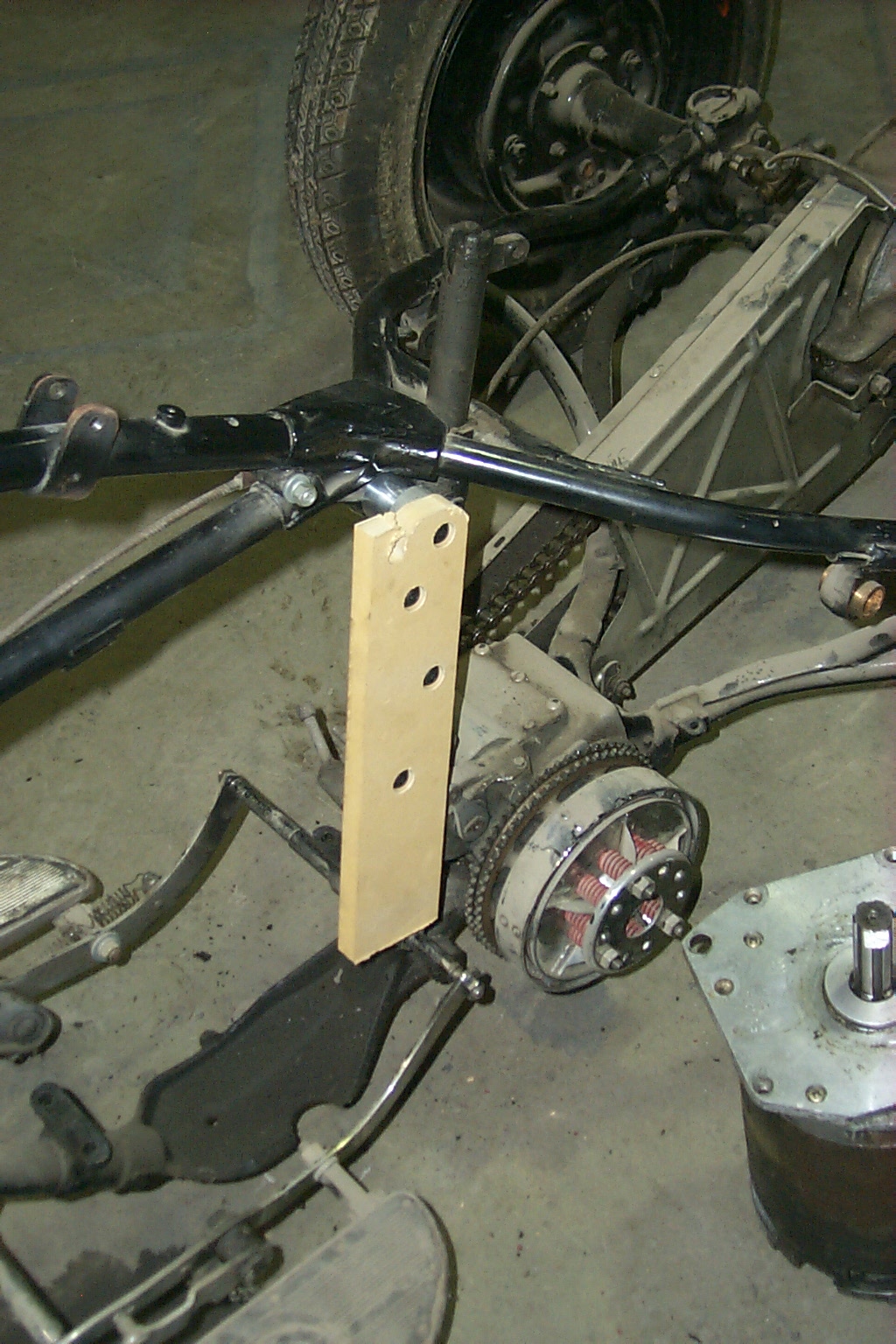
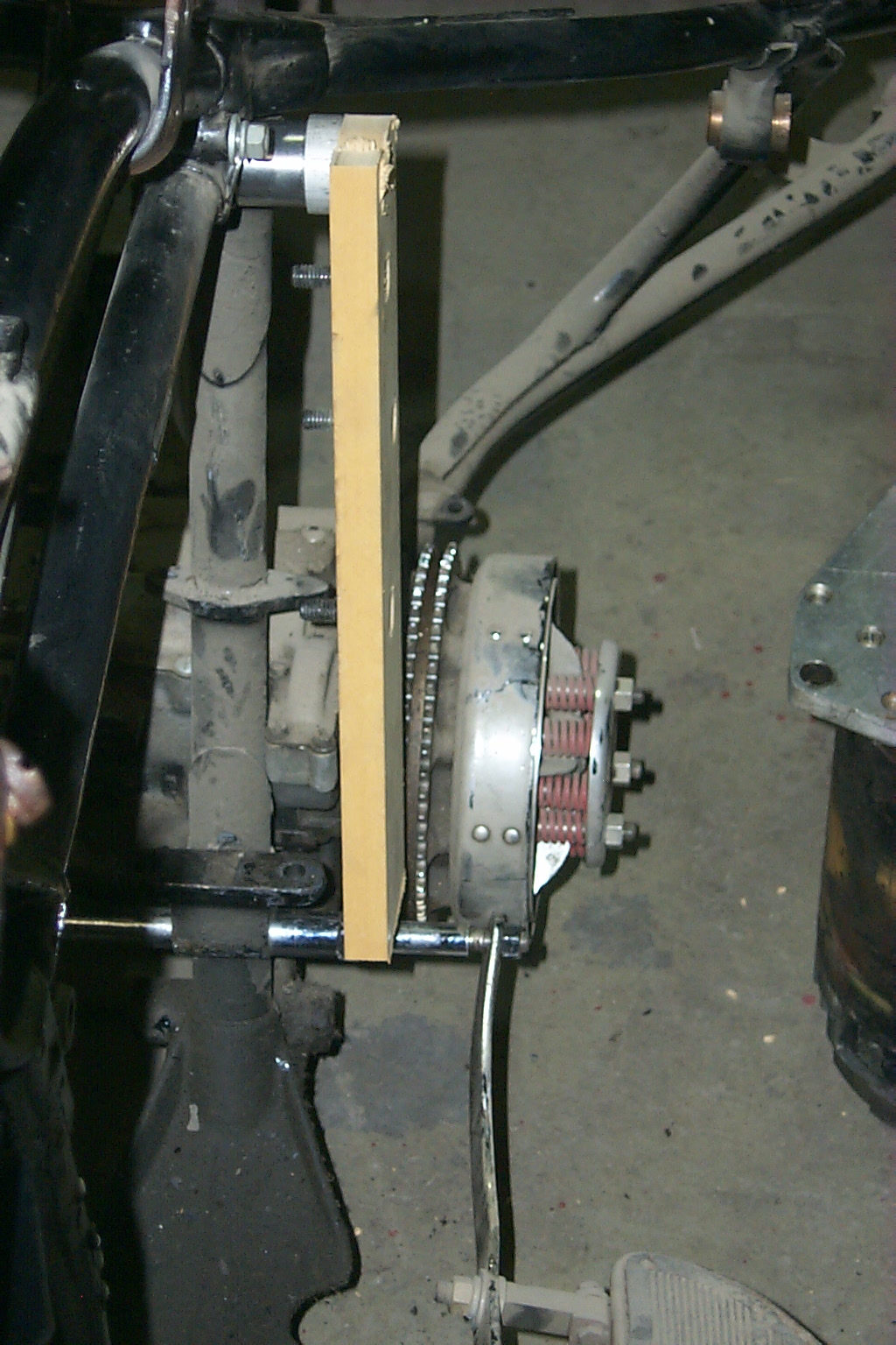
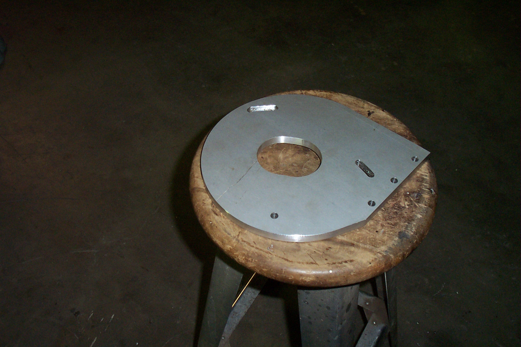
Above is a test mount being made out of medium density fiberboard (MDF) to make sure the dimensions are right for the motor mount and below is the pattern being tried on the motor and the frame.
This allowed me to check the clearance for the drive chain as well and I found I needed to shorten the top mount a little to make the clearance.
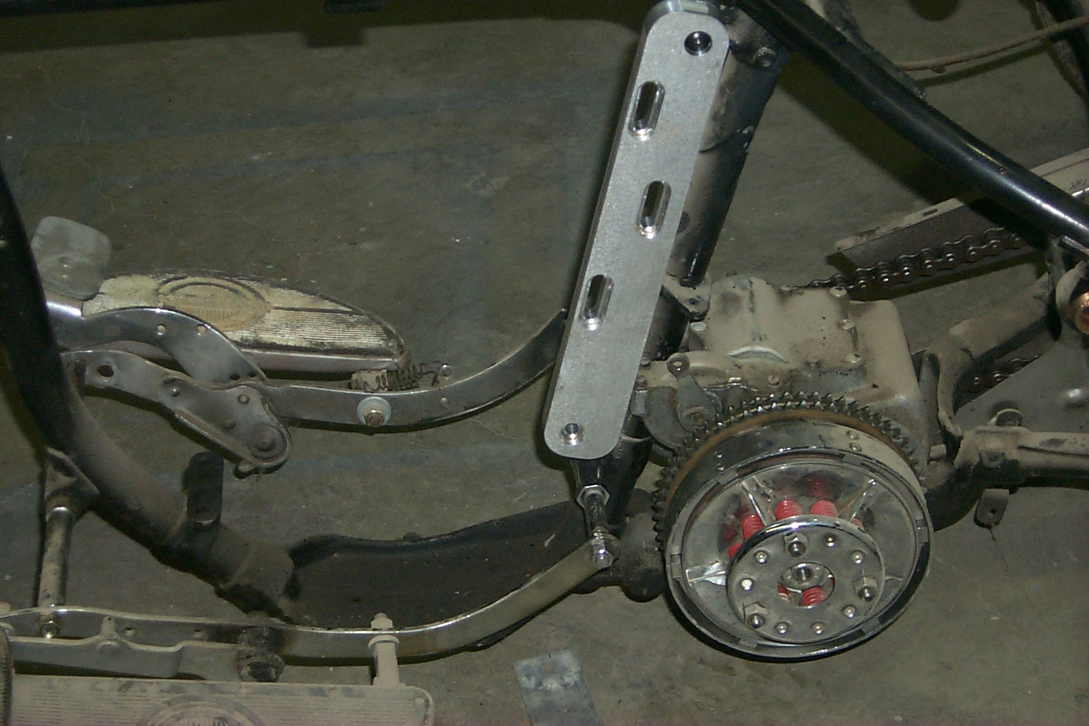
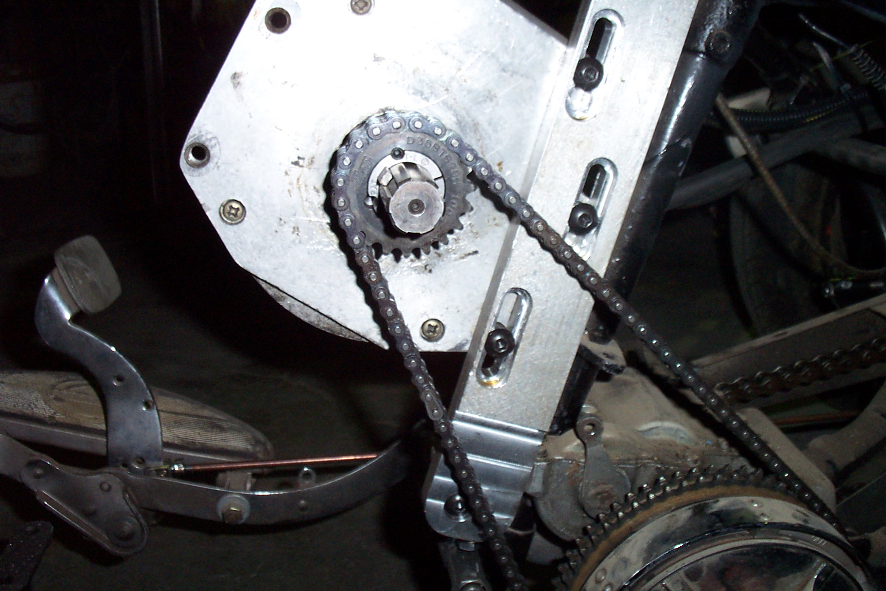
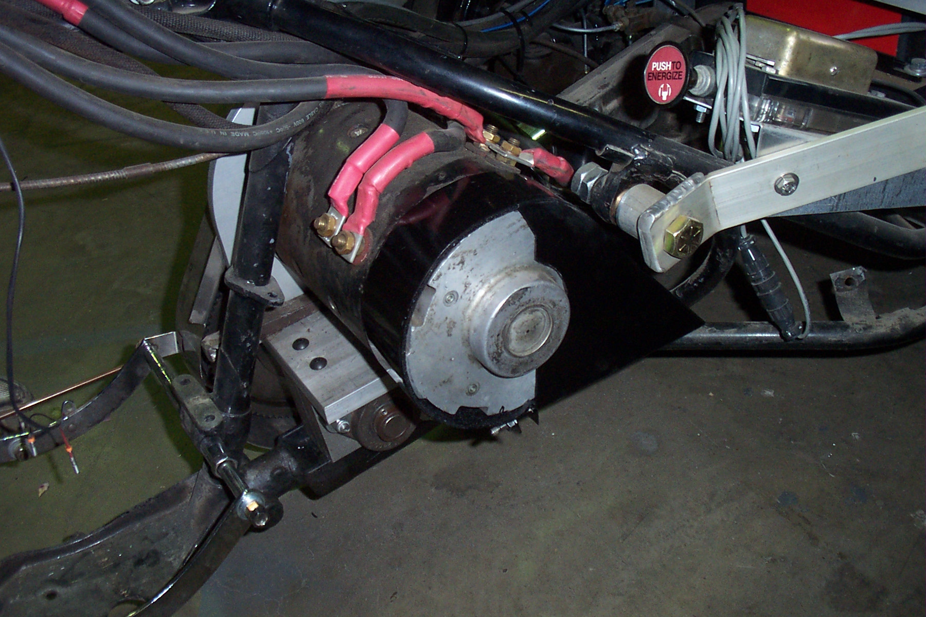
Here is the motor mount as finished in aluminum on the left and on the right is the motor mounted with the drive chain attached. For now I have used a taper lock bushing with a single key in one of the splines on the motor shaft. If this doesn't hold the torque, then I may have to create a splined bushing with a series of keyway broaches.
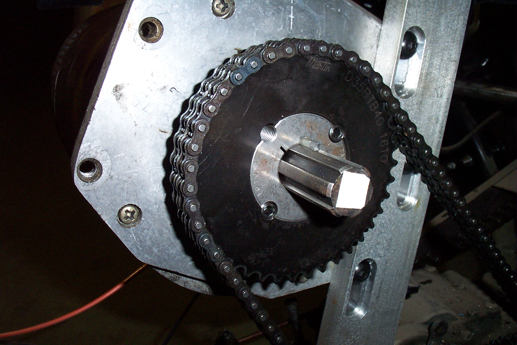
And a close up view of the motor sprocket mount.
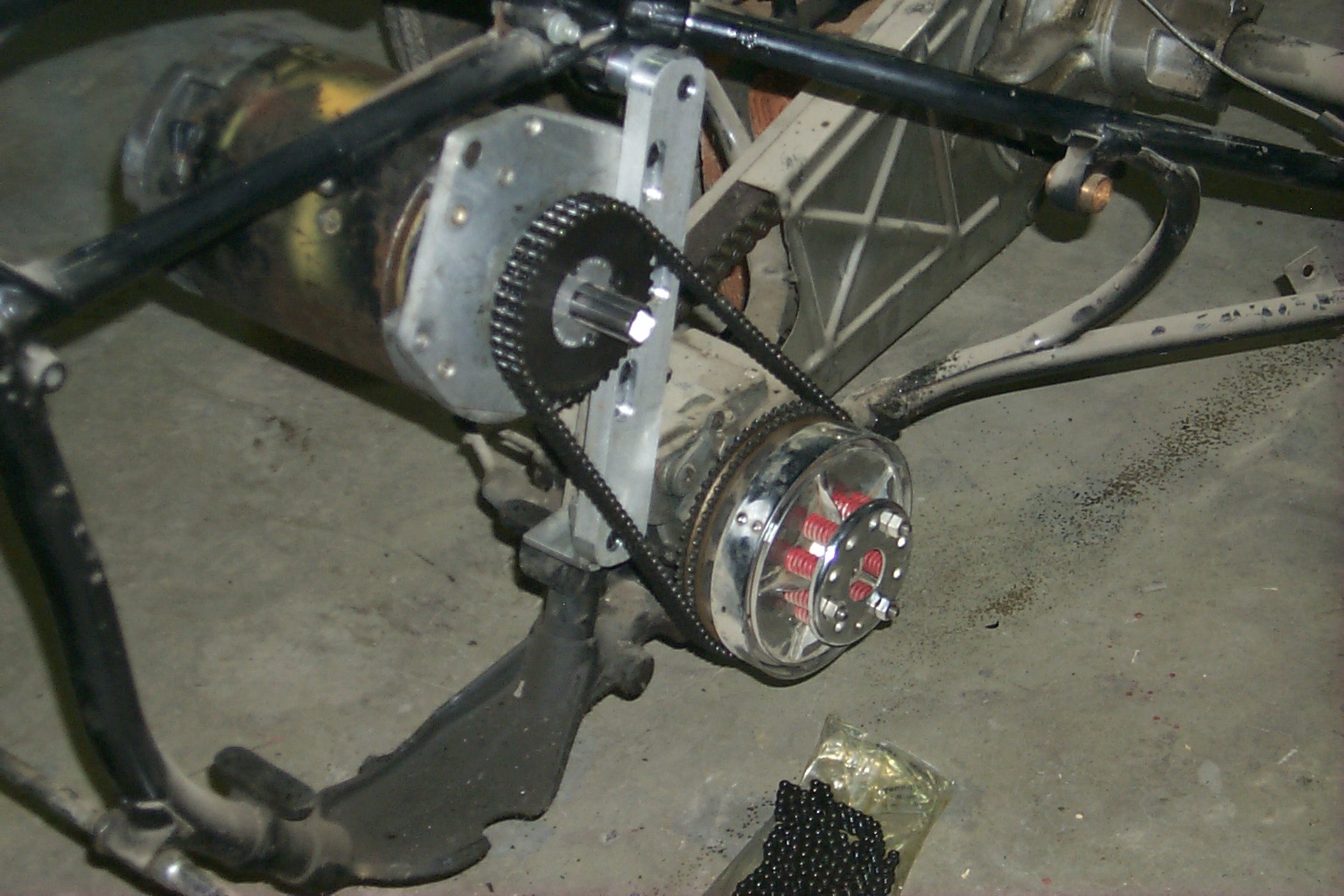
I have been able to jack up the rear end and spin the wheels with a 12 volt battery and now the next step will be to address the brake problems. I can't even drive it across the drive way without a way to stop it! I changed the drive sprocket to 20 tooth after the first test drive since I was afraid of the current draws I was seeing. Below is a picture of the smaller drive arrangement, but I have since changed the drive back to the 40 tooth shown above.
June 06; I have now changed the drive system to get rid of the transmission and mount the motor behind the seat post. This will leave the "motor bay" empty and I will either use the space for a battery charger or maybe a hamster wheel for fun.
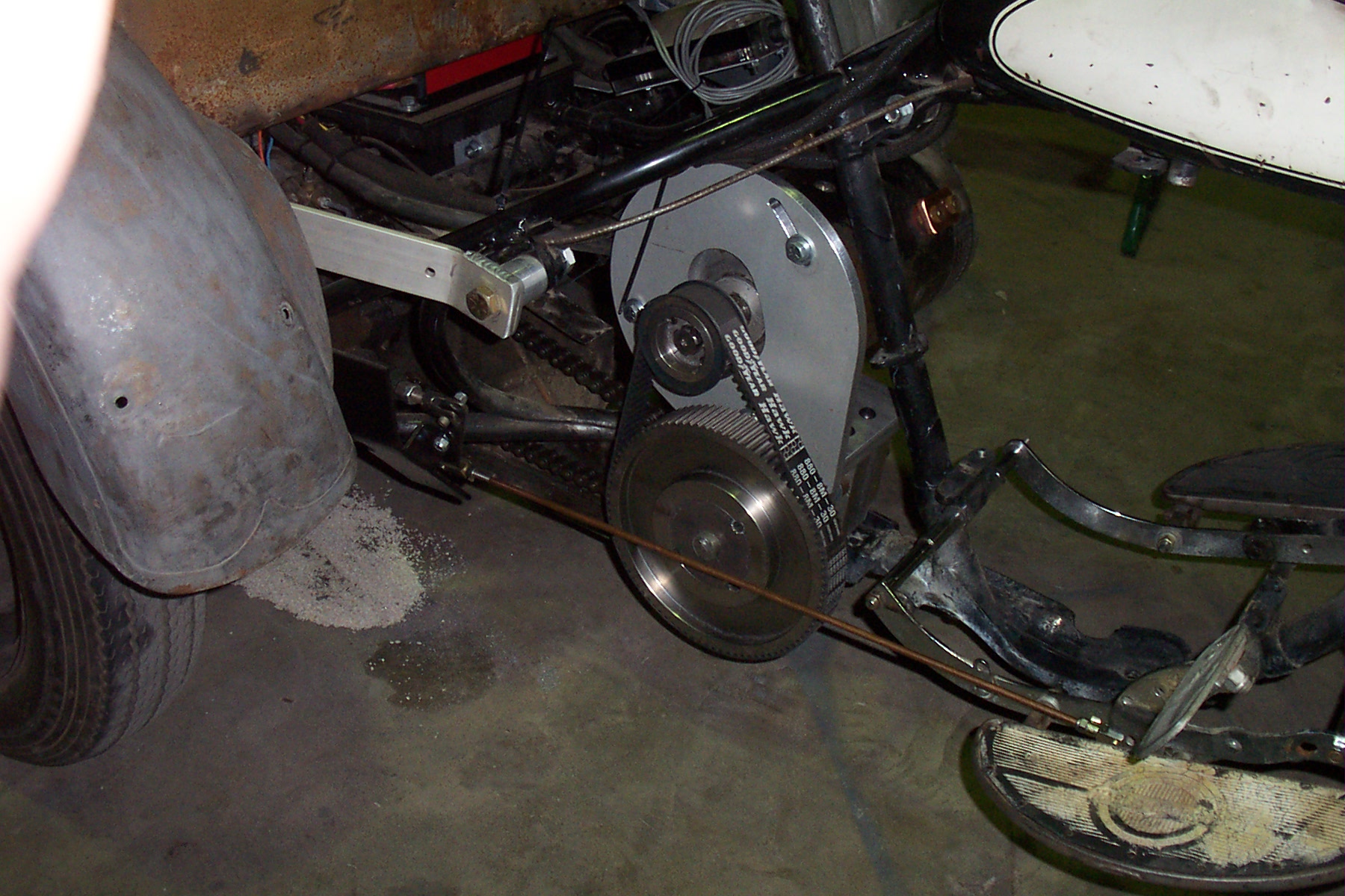
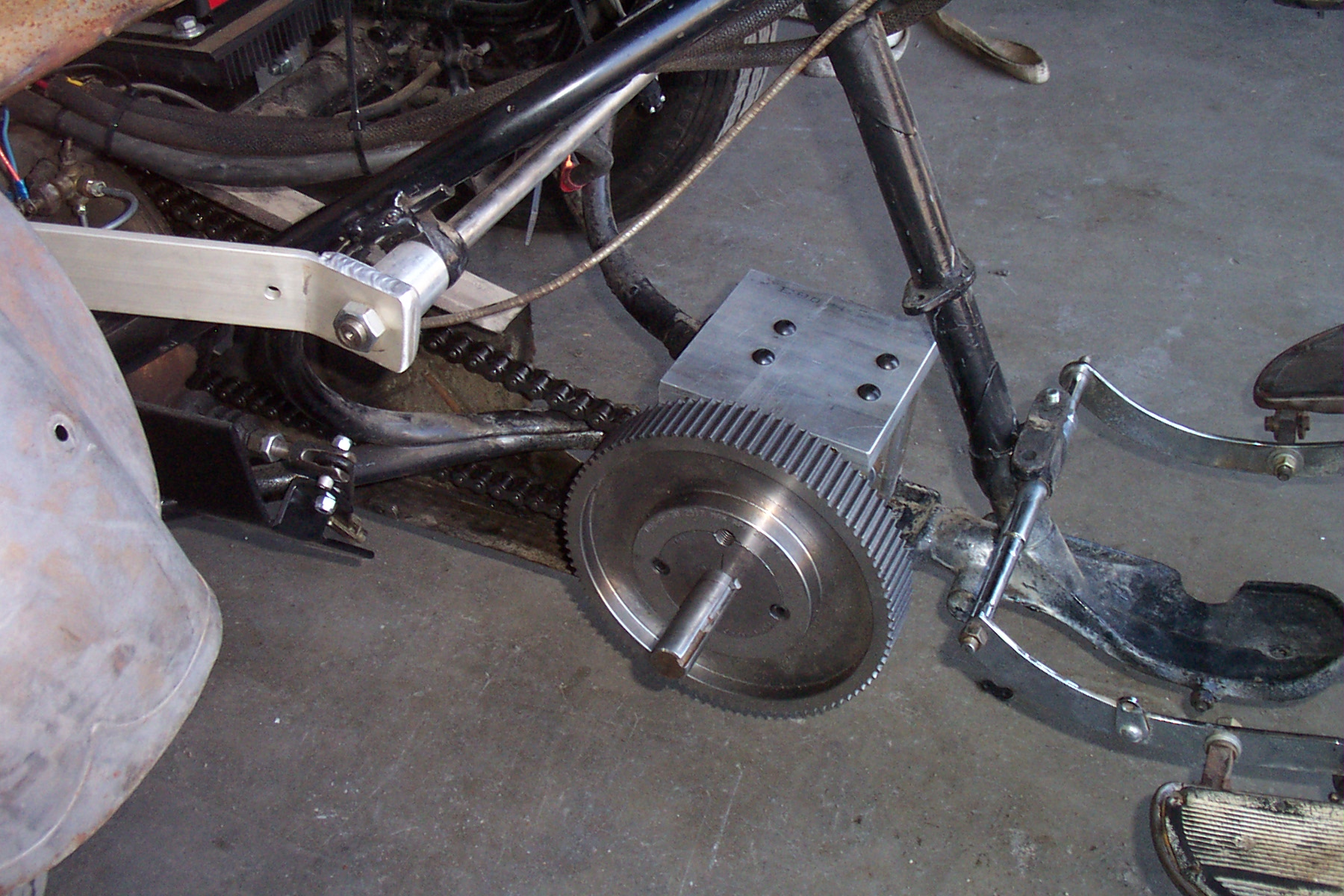
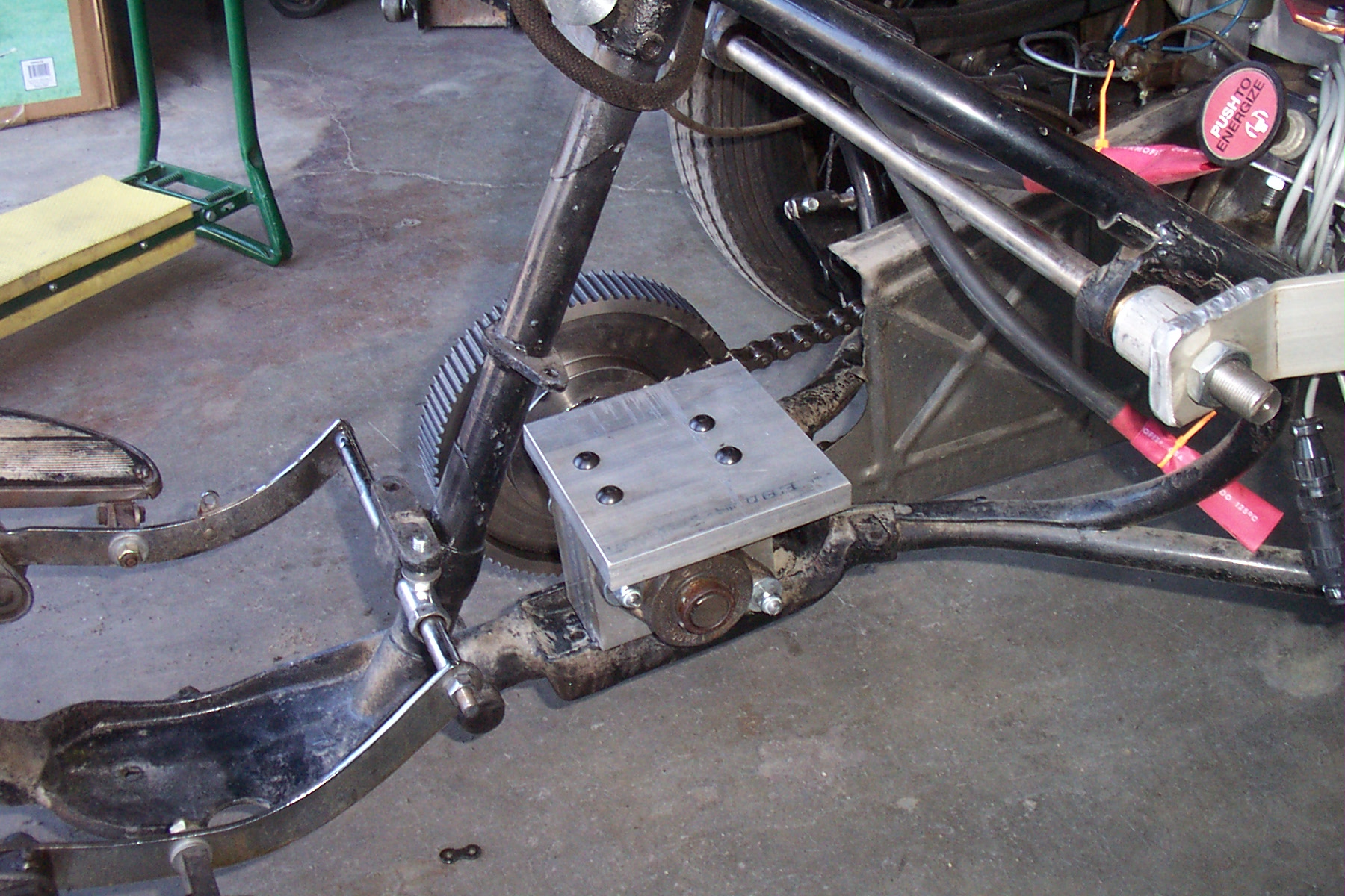
The primary drive is a toothed belt with a 3:1 ratio to a jack shaft and the rear drive is still a #50 chain with a 2.64:1 giving me an overall ratio of 7.93:1. This may still be too high and I may take the rear ratio up a little as I think I can get another tooth or two off of the driving sprocket. The jack shaft is mounted through a block of aluminum with flange bearings on either side. The top is drilled and tapped to hold a base plate for the motor mount and the bottom is drilled and tapped for the existing transmission mounting arrangement. The motor mount is bolted to the edge of the base plate and is slotted for belt tension.
Above are views of the jack shaft mount and motor base plate from both sides of the bike.
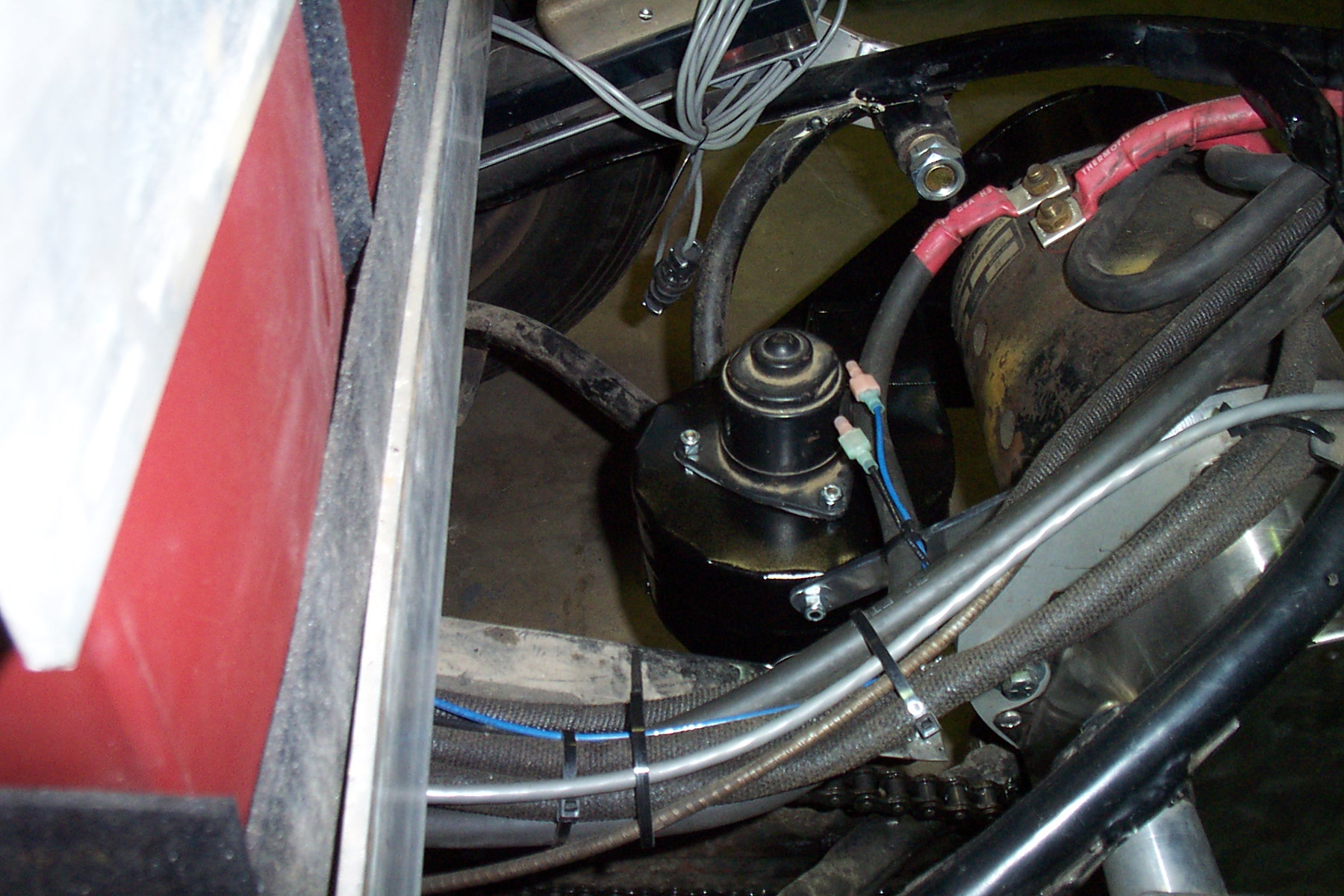
Since I removed the transmission, I lost the reverse gear so I am adding a reversing contactor set. I have put the information on that modification on the wiring page. After the first 40 miles or so, I determined that I needed a fan on the motor for extra cooling. I used a small 12 volt heater fan from the wrecking yard and built a shroud and ductwork to direct it into the brush end of the motor as shown in the pictures below.
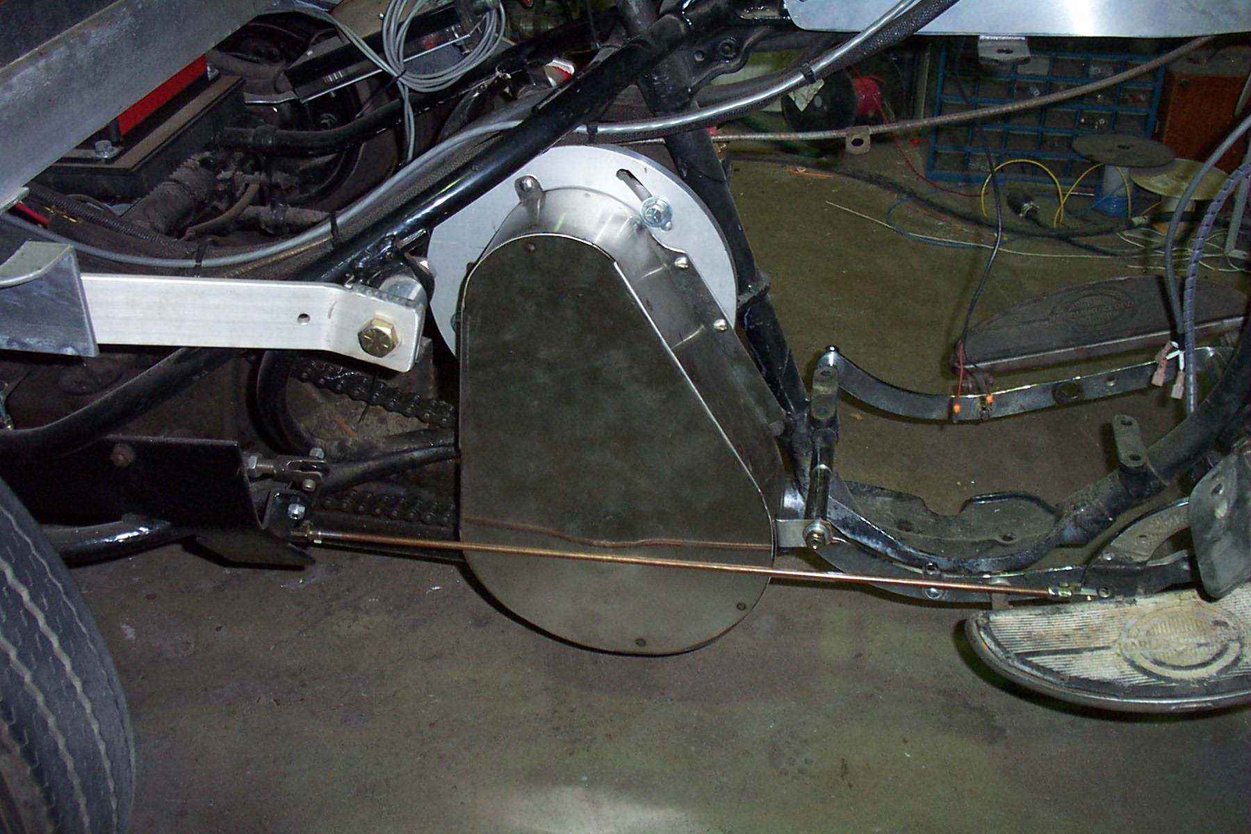
At some of the show and tells I have had people mention their concerns about the open drive system so while waiting on the body and paint I made a belt guard for the primary drive.
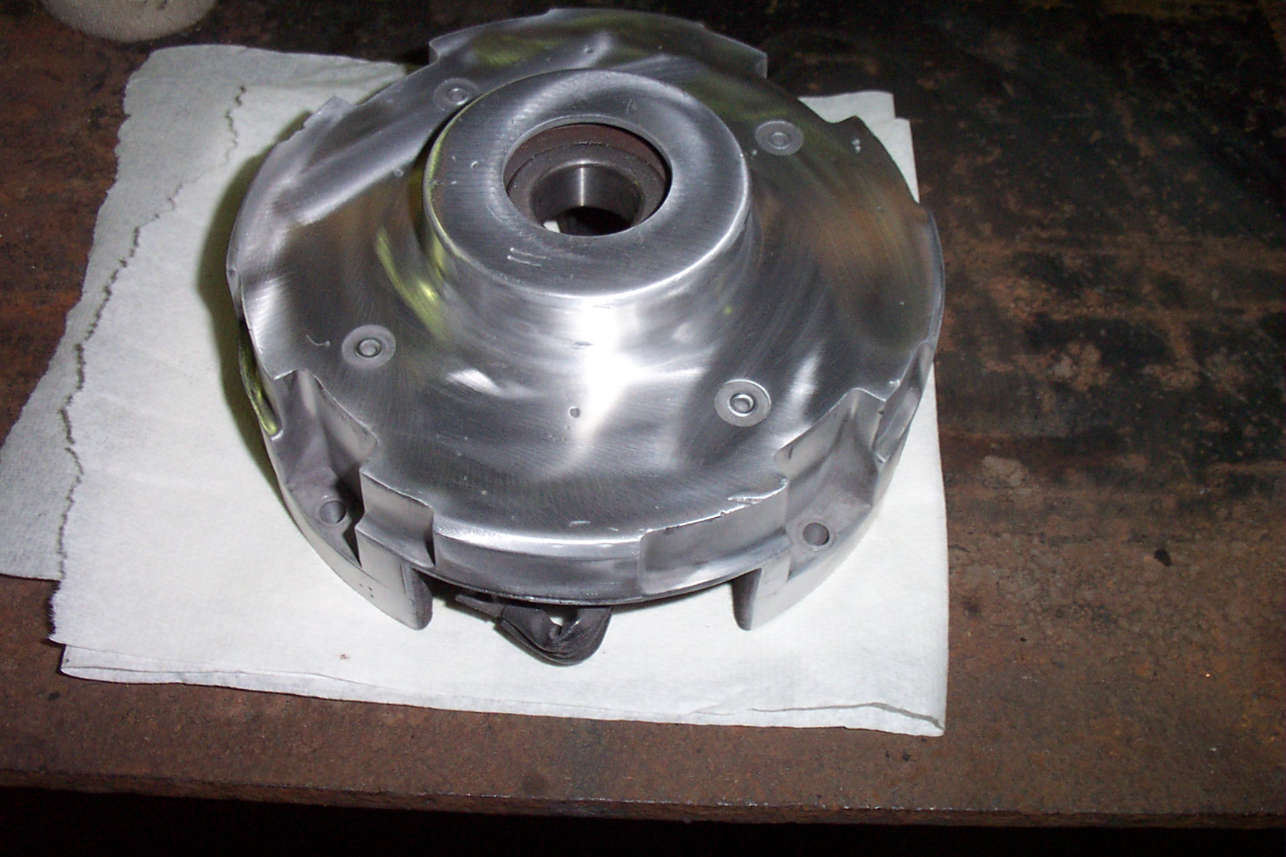
After the body and fenders came back, the motor started looking pretty bad so it got a paint job as well. It was a good thing since I found a bit of wear on the inside of the end bell where the new bearing was rubbing. A few minutes on the lathe took care of the clearance problem. I can't say for sure, but I expect it also helped my range by removing that little bit of drag. I know it will allow the motor to work much longer. The end bell also got a quick polish job too while it was apart. It will tarnish since it is aluminum, but it looks good right now.
|